

AM radio stations around the country are considering a switch to all-digital AM broadcast technology, an option since October 2020 when the all-digital AM service, using the HD Radio digital technology developed by Xperi, was authorized by the Federal Communications Commission (FCC). One potential challenge AM broadcasters having directional antenna arrays might face in a conversion involves the optimization of the antenna amplitude and phase characteristics for all-digital operation.
A session at this year’s NAB Broadcast Engineering and Information Technology Conference (BEITC, April 23-27, 2022, Las Vegas, Nev.) entitled “AM and FM HD Radio” included a paper, excerpted here, presenting new data which may assist in this optimization. This paper is titled “Exploring the Effects of Directional Antenna Pattern Bandwidth on MA3 Transmissions,” and was co-authored by Dave Kolesar, senior broadcast engineer, Hubbard Radio, and Mike Raide, senior manager, Broadcast Technologies, Xperi. You can buy this paper for $15 or get all 35 papers in the Proceedings for $75. And as a reminder, if you were an NAB Conference Show registrant, access to the Proceedings was included in your registration for no additional fee via a coupon code.
INTRODUCTION – In this paper, an effort is made to characterize a received signal on- and off-axis to the null direction of a directional AM antenna array in order to document the real-world failure conditions of all-digital AM (also referred to as MA3) transmissions. By examining the received signal using a spectrum analyzer and a test receiver that monitors the received signal constellations, the maximum tolerable distortion with regards to amplitude and phase can be characterized. It is hoped that such data will be of use in the design or modification of antenna systems where all-digital AM operation is contemplated.
THE ANTENNA SYSTEM – These tests were done using the WWFD (820 kHz, Frederick, Md.) nighttime antenna system, consisting of two towers (see photo below). Power is fed to the antenna system via a simple Ohm’s Law power divider, with the phase to each tower adjusted via T-networks, forming a cardioid pattern. Since the null in this pattern is rather deep, it is instructive to examine how the station’s MA3 transmissions perform on and adjacent to the null’s radial. Such “real world” data from a necessarily imperfect antenna system adds to the knowledge base as to when all-digital MA3 reception fails due to inadequate null-fill in the array.
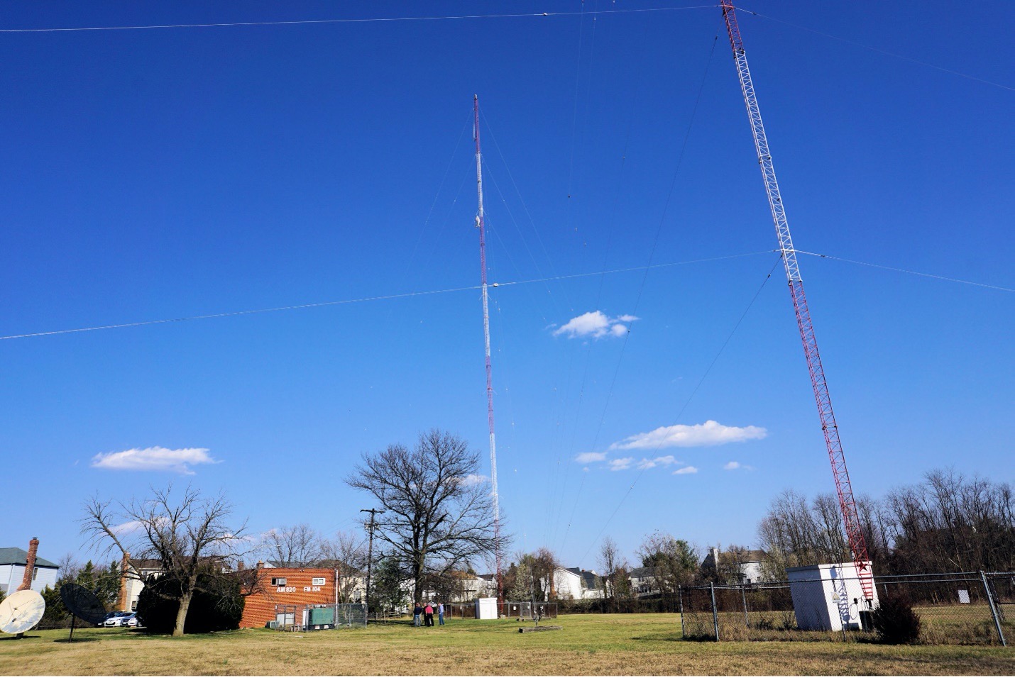
Two-tower array of station WWFD, 820 kHz, Frederick, Md
TEST PROCEDURE – A test vehicle is outfitted with an omnidirectional, medium wave loop antenna mounted as close to the center of the roof as possible. This antenna feeds a test receiver capable of depicting the signal constellations, as well as a spectrum analyzer to monitor the amplitude linearity of the received signal as shown in the figure below. A test route is chosen that sweeps through the null of the antenna system, starting from the north and proceeding south.
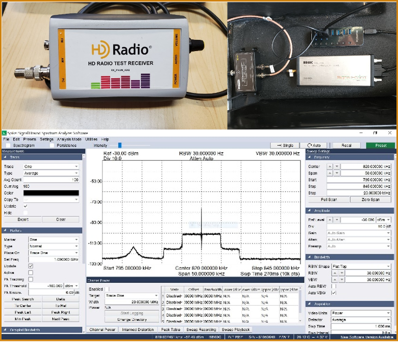
HD Radio test receiver (top left), spectrum analyzer hardware (top right) and spectrum analyzer screen shot (bottom).
The vehicle is then driven south and stopped for stationary measurements at several places, including the three designated monitor points, which are along the 268, 253 and 238 degree radials. The vehicle is driven south until reception quality approximates the first point, indicating that the vehicle has travelled through the subtended azimuth angle where reception is impaired by the poor pattern bandwidth and null-fill performance of the antenna system. At each point, reception quality of the monitor radio is noted and a field strength measurement is taken. A spectrum analyzer screenshot is taken to measure the amplitude ripple of the channel.
RESULTS – In examining the spectrum analyzer plots for the various test points, it can be seen that the MA3 signal can be decoded despite fairly adverse channel transmission characteristics. In the WWFD test data, an amplitude ripple of 4 dB within one carrier set seemed to be compensated for by the synchronization and equalization processes in the receiver.
Despite the redundancy built into the MA3 transmission system, antenna system engineers and designers should not overlook the pattern bandwidth and null-fill characteristics of AM directional antenna systems. In the areas of marginal array performance, reception robustness is lost. Ensuring maximum impedance bandwidth as well as pattern bandwidth is a must for any all-digital AM transmission system. Such efforts will pay off by creating the best listener experience by maximizing the useful coverage area of an AM station with a directional antenna system.