

PILOT has developed a state-of-the-art AM and FM radio test bed that is available for hire. This facility is located in Washington, DC in the NAB Technology Lab, located on the fifth floor of the NAB headquarters building.
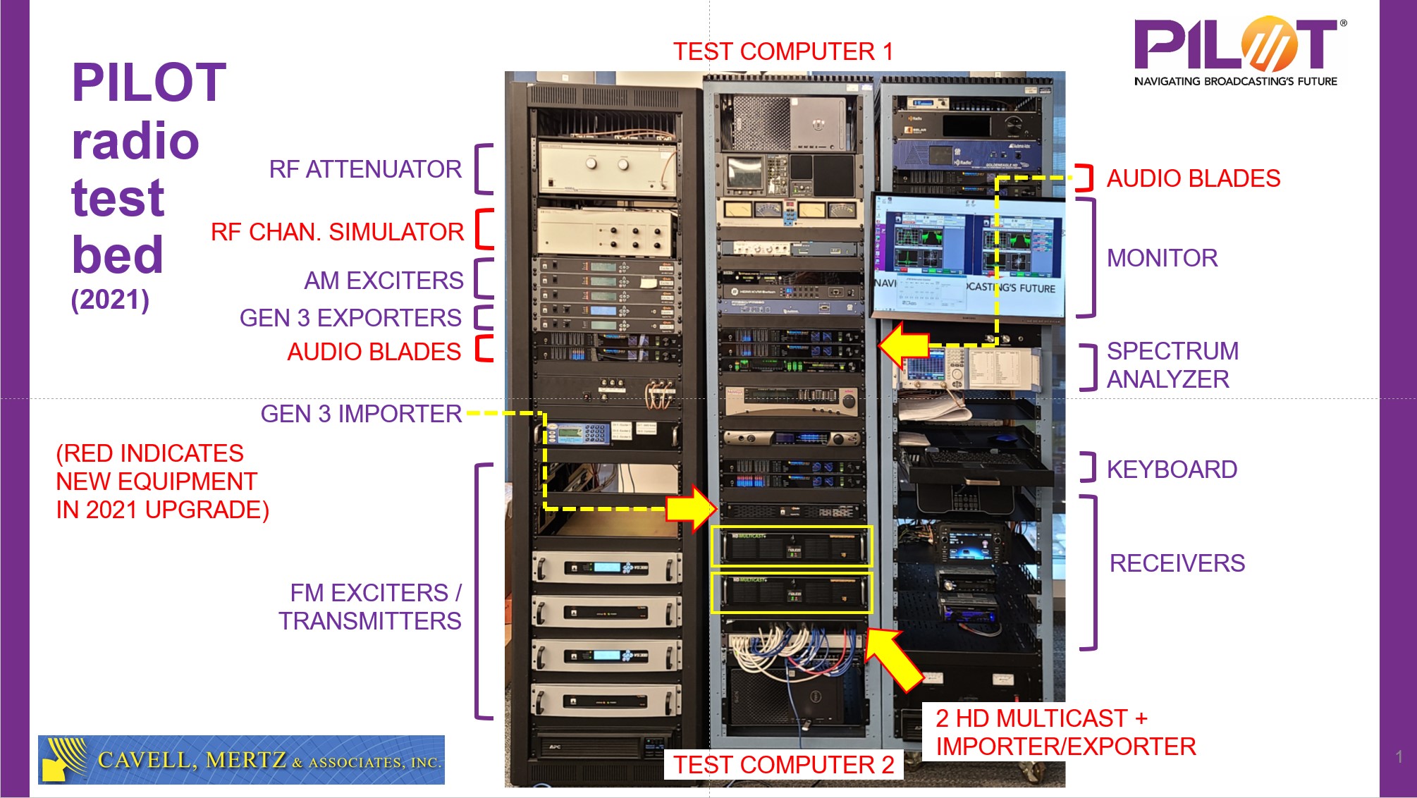
PILOT Radio Test Bed shown after the upgrade done in 2021
Originally built in 2014 by Cavell, Mertz and Associates for AM band testing, it was upgraded for FM band testing in 2016 and underwent additional upgrading in 2021 when it was moved from its original location in Manassas, Virginia to the NAB building. The PILOT Radio Test Bed is particularly well-suited for conducting adjacent-channel interference testing. For each band, the test bed includes three RF exciters allowing for tests involving simultaneous upper- and lower-adjacent channel interferers (in addition to a desired signal). Additionally, the test bed is capable of HD Radio transmissions in both bands, and includes a set of “gen 3” HD Radio Importer and Exporter gear as well as two “gen 4” HD Multicast+ units.
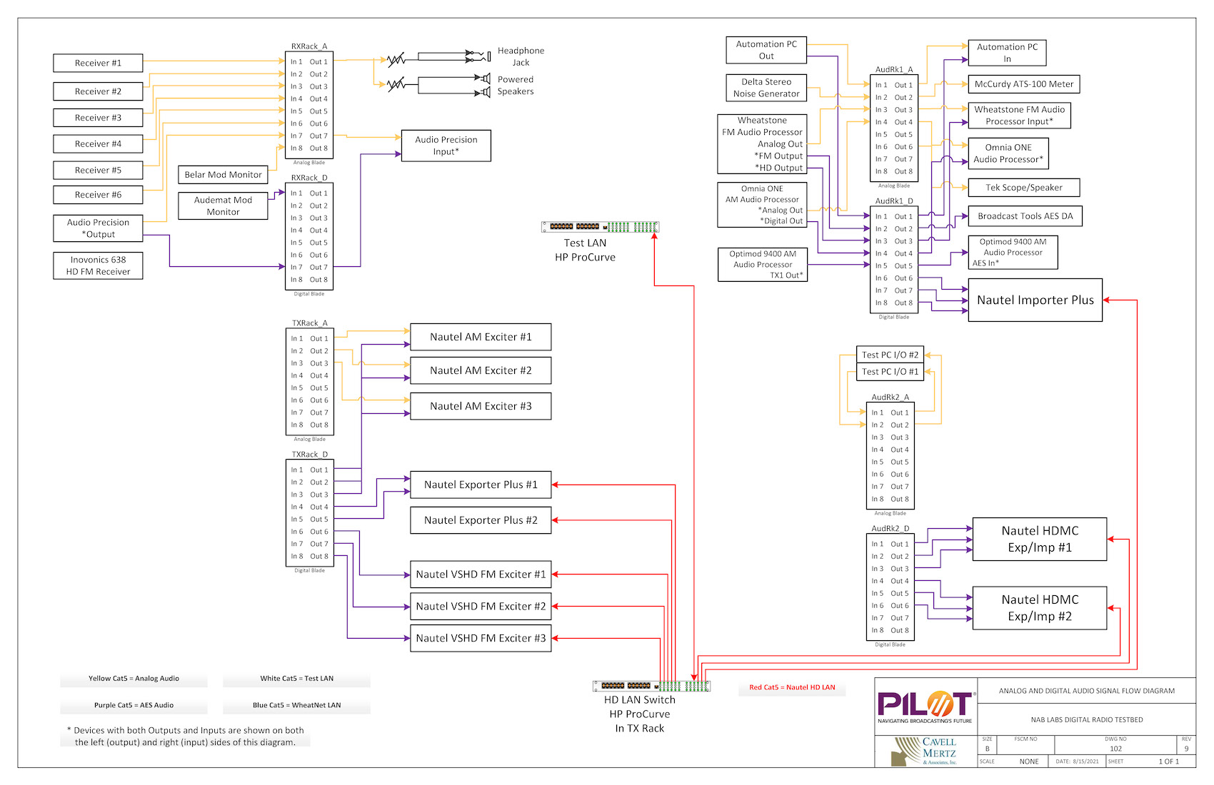
Audio signal flow diagram – audio distribution is accomplished using audio blade technology.
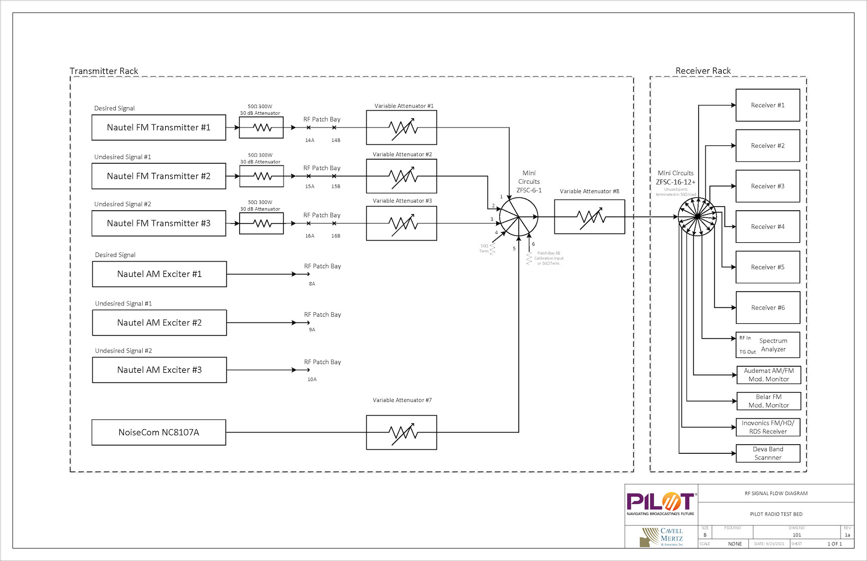
RF signal flow diagram – test bed is designed to operate with either AM or FM radio signals (one at a time)
All of the test bed hardware is contained within the three equipment racks shown above and described here:
- The transmitter rack (leftmost) contains the RF generation equipment including three AM exciters, three FM Transmitters & HD Exciters, Exporters, RF attenuators, RF patch panel, RF noise generator, and a 6 port RF combiner. Added during the 2021 upgrade were analog and digital audio blades and an HP 11759C multipath simulator. This rack is powered by a dedicated UPS also mounted in this rack.
- The audio rack (center) contains the audio router, additional analog and digital audio blades, audio test and measurement equipment, automation and control computers, three audio processors, an audio noise generator, and an RDS encoder.
- The receiver rack (rightmost) contains an 8-port RF splitter fed from the transmitter rack combiner, five test receivers and associated 12VDC power supply, modulation monitor, RF spectrum analyzer, keyboard and monitor for all computers in the test bed (controlled through a KVM switch), additional analog and digital audio blades and a UPS that powers both the audio rack and the receiver rack.
If you are interested in hiring the PILOT Radio Test Bed, please contact David Layer at NAB.